Do not expect updates so close to each other, but tonight I just finished the first part of entering data in JMRI, so I thought I would give you an update.
Once I decided to start this project, I knew that it would have to be not too complex. My goal is to learn things about automatic running (specifically, but also about JMRI, Digitrax, and DCC in general) that could then be applied to David's layout, in a much more complex way with 30 scheduled trains making stops, terminating, going into yards (and dreaming of them being switched …. !!!!).
But to get there I knew I needed to go with something smaller and much less complex, so 3 trains with a small schedule. That should be simple enough, right?
I put pencil to paper (yes, I am old school), and drew a loop. Then added a siding and then another, and pretty soon I had a starting point. I counted the turnouts, and I had 8. I decided to have half the layout viewable, while the other half would be hidden (staging). Because of that, I did not need signals in staging. So with 6 out of the station and 2 inbound to the station, I have 8 signals. Of these, 2 will be main line (7039), 4 approach only (7040) and 2 main/approach (7041). All will be arm type; I am debating to use 2 distant signals (7036) in front of the inbound signals at each curve.
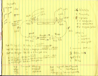
The next thing was to divide the layout into blocks, for the sensors. I came up with 26 blocks. This may change, but for now that is what I decided. Each station/staging track has a "stopping block" at each end. They are not really necessary, but David uses them, so I thought of putting them in. I have 1 at each end of the main station/staging block. That is an extra 12 blocks. I also have the turnouts pairs (4) as blocks.
The next page shows the naming I used with the following convention:
C - Curve
T - Turnout
ST - Staging
DP - Station (Depot)
E - East
W - West
There is also a B#, but I am not using that. I was thinking of using the Layout Editor in JMRI, but I never used it before, and I was told that is not as featured as Control Panel Editor. Plus it cannot run warrants, which is what will be used on David's layout.

Instead I used Occupancy Blocks, or OBlocks. Below is a screen shot of the OBlocks table when the blocks, portals and paths are created and set. The warrants use this information to run trains.

Below you see the definitions of the tunouts and signals. I just realized though that the Marklin signals are actuated by relay, just like the turnouts. In JMRI the signal masts controls the aspect of the signals, the actual lights. So I may redefine the signals as turnouts, but I am not sure at the moment, since the signals will be really for show and will not interact with the running of the trains. Maybe.

So that is all I have done so far from the software side. I also acquired a lot of hardware: BDL168and DS54 (enough for all sensors, turnouts and signals), PM42 (I have not decided how many districts I will be using - hopefully 4 are enough as I have only 1 PM42 for now), DCS200, PS2012, a bunch of throttles.
From the Marklin side (let's not forget that this is a Marklin-Digitrax hybrid project), I successfully converted my DB E41 (3034) with the Marklin DC kit 60943, and a Digitrax DH126 decoder; I will be placing a Power Xtenders (also known as keep alive caps). I will run some initial tests soon once I get the space for setting up a simple loop for testing engines and cars (They have been sitting in boxes for over 30 years - I found 2, so far, engines that were completely frozen with crystallized grease).
The trains will be:
Freight - it will have 5 mix freight cars, with steam engine BR 81 (3031)
Local - it will have 3 coaches for commuters with steam engine BR 86 (3096)
Express - it will have 3 coaches, 2 2nd and 1 1st, baggage, with steam engine BR 01 (3048)
I will also have E 41 (3034) for the express, Railbus and trailer (3016/4018) for the local and E 104 (3049) for the freight.

Hi Leo,
ReplyDeleteThe signals are indeed driven by relays. In my JMRI setup, I use single output Signal Heads defined with a turnout address programmed into a DS64 for driving the actual signal coils. Again, to make this work, you need to isolate "ground" and light for the bulb from the relay coils, but that's pretty straight-forward, see https://blog.lostentry.org/2011/08/semaphores-installed.html
Bernhard
Thank you Bernhard. In fact I was having dinner last night and was thinking about the signals, and that unlike the M track turnouts (though possible), the signals do not have to be connected to the track. Of course the C track is plastic, so it would not matter. I am still considering them as being for visual effect and not for actually controlling a train.
DeleteOh absolutely! The signals should not actually control the track power (contrary to traditional analog maerklin wiring), since you are planning to do that with the computer.
DeleteThe bulb(s) in the semaphores won't be lit when connecting the coils to a DS64, since there is no constant power, and the coils should not be tied to the track through the bulb either. Hence you want to connect one side of 16V AC to the grey wire on the signal, and the other to the signal base, which should not touch the track either.